Hardware → New BIOS mod (unlock G1)
Данный мод теперь не актуален, если вы хотите сделать BIOS mod, то воспользуйтесь старой схемой.
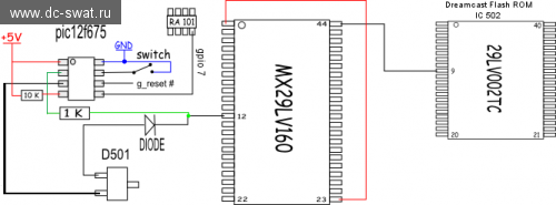
Вам нет необходимости полностью переделывать свой старый BIOS мод, это просто доработка. А если у вас не было BIOS мода раньше, то берём MX29LV160, поднимаем 1-ю,12-ю,44-ю ноги накладываем на родной BIOS и аккуратно паяем. Всё остальное думаю понятно из схем.
Внимание: наличие оригинального биоса обязательно, ни в коем случае не отпаивайте его
Вопросы, обсуждение, прошивка для pic12f675
- +1
- megavolt85
- 03 декабря 2014, 09:19
Комментарии (9)
rss свернуть / развернутьAfter as BIOS is auto switched, DreamShell will be executed from RAM.
So you can get maximum compability as on original BIOS and working HDD/GD without problems.
But need updated BIOS firmware with DS core (ds_core_pic12f675.bios), you can get it from GitHub or forum.
свернуть ветку
You said that «you CAN Get Maximum compability » then it means this New BIOS mod would allow to execute more game successfully than old Bios mod in Dreamshell iso?
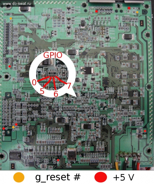
And what does mean of GPIO 0 5 6 7 on your screenshot?
IS GPIO not the same with pic12f675's pinout like below link and GPIO means specific pinout?
pinout-circuits-images.dz863.com/43/PIC12F675.jpg
свернуть ветку
(for example Can I use Current Regulator Diodes 1N5310 or 1N4148 (100V)or 1N4001,1N4004 for this BIOS MOD?
свернуть ветку
with latest bootloader BIOS and DS_CORE.BIN from GitHub.
свернуть ветку
By the way,I plan to solder at the edge of IDE ribbon cable with the 40 pin IDE device's soldering point, which dreamcast mainboard has,like below «plus.google.com» links
plus.google.com/u/0/photos/+LesRailton/albums/6021215859466875073/6021215863533972226?pid=6021215863533972226&oid=106929866019169011552
But There is G1-ATA(IDE) adapter in your site
www.dc-swat.ru/blog/hardware/874.html
Is there any crucial difference between «just wiring IDE interface» and stick «G1-ATA(IDE) adapter» into slot from GD-ROM?
Does stick G1-ATA(IDE) adapter into GD-ROM's slot" has superior compatibility than «just wiring IDE interface/cable to DC mainboard» for running GDI or ISO image files in Dreamshell ISO?
And Should I try any Bios mod in order to run GDI or ISO image from IDE 40 pin's HDD?
For your information I have a dreamcast which is marked as «IC BD KATANA MAIN V1 Made in Japan» and it has still working GD-rom.
свернуть ветку
BIOS mod is not required, you can launch boot loader or DS core from CD and put other DS resources to HDD.
свернуть ветку
YOU ARE THE KING in the Dreamcast Hacking Scene!
свернуть ветку