Hardware → Sega Dreamcast & NAOMI SCI-SPI Mod
This guide explains how to access the SH-4 SCI port on Sega Dreamcast and NAOMI systems in both UART/SPI communication modes. It can be used for debugging or connecting an SD card. In SPI-like mode, the SCI port can transfer data at speeds up to 1.5 MB/s, which is twice as fast as using the SCIF port for bit-bang SPI.

High resolution image.
On the same resistor array as the CS line (RA101), you can also solder to the other pins of this array to access additional SH-4 GPIO lines: GPIO0, GPIO5, GPIO6 and GPIO7 used as CS. This is useful for expanding control or using additional chip-select lines for multiple devices in future.


The MOSI/MISO wires are mixed up in this photo, sorry =).
Additional wire is GPIO 0
Thanks to ElectronAsh fo NAOMI CN1 pinout and megavolt85 for Dreamcast SCI and GPIO pinout
Sega Dreamcast Motherboard
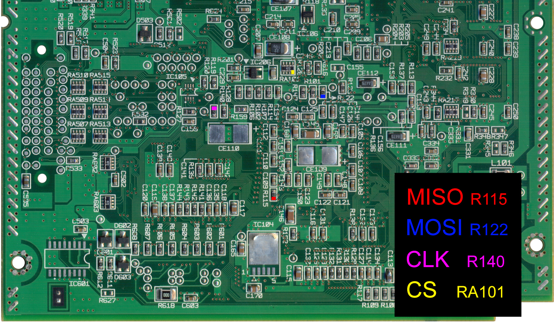
Solder wires directly to the following points on the Dreamcast motherboard:High resolution image.
| Signal | Function | Pad Label | Color Code |
|---|---|---|---|
| MISO | Data In | R115 | Red |
| MOSI | Data Out | R122 | Blue |
| CLK | Clock | R140 | Purple |
| CS | Chip Select | RA101 | Yellow |
On the same resistor array as the CS line (RA101), you can also solder to the other pins of this array to access additional SH-4 GPIO lines: GPIO0, GPIO5, GPIO6 and GPIO7 used as CS. This is useful for expanding control or using additional chip-select lines for multiple devices in future.
Sega NAOMI and NAOMI 2 CN1 Connector
SCI (and also SCIF) signals are available on the CN1 connector without any soldering:
| Signal | CN1 Pin | SH-4 Function |
|---|---|---|
| MISO | B45 | SH4_RXD |
| MOSI | A46 | SH4_MDI7/TXD |
| CLK | A47 | SH4_MDO7/SCK |
| CS | B50 | SH4_MD8/RTS2 |
SD Card pinout
Wiring & Notes
- 3.3V logic level only — use level shifters if necessary.
- For power, it's better to use a 5V to 3.3V DC-DC converter for the SD card, since both Dreamcast and NAOMI systems place the highest current load on the 3.3V rail.
- The length of the wires should not exceed 15-20 cm.
- For NAOMI, the CS line uses the RTS signal from SCIF, since no GPIO pins are available on the CN1 connector.
Example
The MOSI/MISO wires are mixed up in this photo, sorry =).
Additional wire is GPIO 0
Thanks to ElectronAsh fo NAOMI CN1 pinout and megavolt85 for Dreamcast SCI and GPIO pinout
- 0
- SWAT
- 09 мая 2025, 09:09
Комментарии (0)
rss свернуть / развернуть